Battery Management System (BMS)
The core of every battery is the battery management system, it monitors the battery and ensures ideal and safe operation of the battery system.
The battery management system is the brain of the battery, so to speak. It monitors the condition of the battery and ensures efficient operation and a long service life via cell balancing.
Core competencies of the Futavis BMS: Safe, efficient, durable and flexible
Safety:
- Ensuring the ideal operation of the battery
- Protection against incorrect use and thus avoidance of permanent damage to the battery
- Application of different safety mechanisms according to ASIL C: such as redundancies, regular communication checks
- Certified functional safety according to ISO26262, EN ISO 13849, EN ISO 62061, EN IEC 60730
Efficiency:
- Low consumption of BMS components (ultra low power mode for CSC ports)
- Fast communication and thus fast responsiveness of the control system
- SOH and SOC monitoring
Lifespan:
- Ensuring operation in the ideal load range (battery level)
- Passive cell balancing
- Control of shutdown scenarios in the event of faults such as overtemperature or overvoltage
- Use of high quality components
- Remote diagnostics for full insight at any time via UDS diagnostics using CAN
Flexibility:
- Modular structure of the BMS
- Any Li-ion cell chemistry can be used
- Individual setting of several parameters of the Futavis BMS
- Multi-string setup with up to 20 masters individually switchable
- Communication via CAN as standard, others possible on request
Futavis manages to make your battery efficient, durable and reliable with integrated circuits and a modular design of the BMS. From engineer to engineer, we are on hand to provide advice and support throughout the development process.
Architecture & Features
The BMS controls the cell voltage, preventing over- or undervoltage. This prevents overcharging or complete discharge of the battery. Both scenarios would damage the battery and shorten your life.
Furthermore, it monitors cell temperatures to prevent overheating or undercooling during charging and discharging.
Via a data bus with the end system, the BMS can pass on recorded and stored data and issue corresponding error messages in the event of faults.

BMS Master
The master is the higher-level control unit of the battery. It includes processing of signals, measurements, communication and control interfaces. One master can control up to 15 CSC boards.
The master is responsible for monitoring and controlling the entire battery system, as well as communicating with the other masters, CSC's and other components of the end system. It determines the battery State of Charge (SOC) and State of Health (SOH), and also monitors cell voltages, currents and temperatures, ensuring safe battery operation. Thus, the shutdown in case of over- or undervoltage, over- or undertemperature can be controlled, the balancing can be implemented and all measured parameters can be stored and processed.
A special feature of our Master is that in a multi-string setup no further Master is needed as Master-Master. One of the masters already present in the system can take over all the functions of the system master. Read more here.
The master uses input signals such as Enable, HV Enable, Charge Enable. HV Interlock. Furthermore, the master provides some additional unused GPIOs for user-defined functionalities.

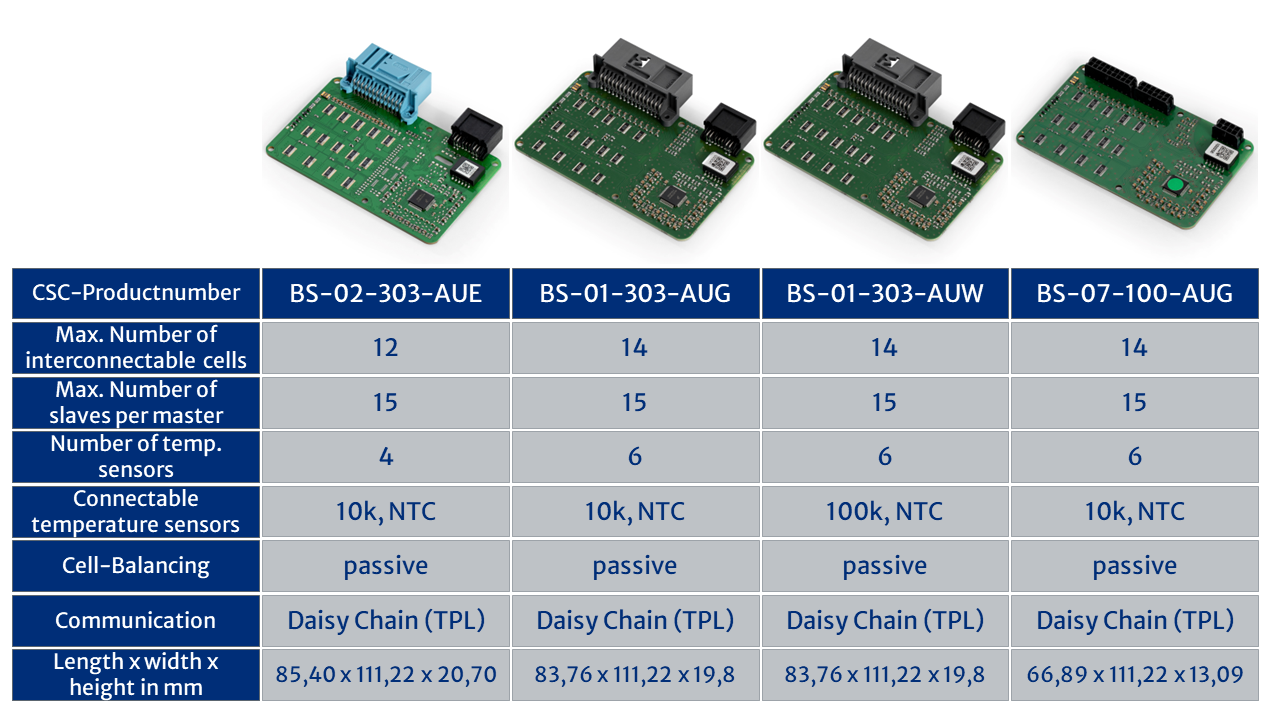
BMS CSC (Cell Supervision Circuit)
The "Cell Supervison Circuit" CSC board is responsible for monitoring the temperature and cell voltage. One CSC board is used per battery module, which usually consists of 7-14 cells. The CSC can provide interfaces and passive balancing for all cells. In addition, each CSC board contains up to six (NTC) temperature sensors.
Since the cells are usually not 100% equally charged, the CSC measures the cell voltages and compensates for the differences by additionally discharging the stronger cells.
The connection between the CSC's and between the first CSC and the master is realized by means of High Speed Differential Isolated Communication.

Modular software construction kit
The Futavis BMS is based on a modular development approach. Starting with the self-developed software and hardware up to automated testing, the Futavis BMS can be quickly and efficiently integrated into the individual customer system.
Comming soon....
